Test of vertical locking hydraulic cylinder
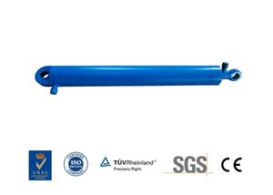
The locking hydraulic cylinder plays a key role in ground equipment products. The vertical locking hydraulic cylinder is used to complete the erection and recovery of the launcher. The quality of its function affects the success of the launch. It is necessary to take measures to ensure product quality as the goal, and carry out various performance tests of erecting hydraulic cylinders during product development. This article summarizes and analyzes the structural characteristics of the locking hydraulic cylinder, summarizes the key performance test items, carries out the research of the test method, develops a set of test equipment, verifies the key requirements of the vertical locking hydraulic cylinder, and ensures the product quality is foolproof.
1. Introduction to vertical locking hydraulic cylinder
The vertical hydraulic cylinder adopts a structure with a built-in locking sleeve, which mainly includes parts such as cylinder barrel, piston, locking sleeve, end cover and piston rod. The locking hydraulic cylinder has two working states: locked and unlocked: when the hydraulic cylinder is in the locked state, the piston rod and the cylinder can be reliably locked, and when the axial load is less than the locking force, the piston rod and the cylinder There can be no relative movement between the cylinders; when the hydraulic cylinder is in the unlocked state, the positive cavity pressure build-up and negative cavity pressure relief piston rod is extended, and the negative cavity pressure build-up and positive cavity pressure relief piston rod is retracted.
1. the formulation of process methods
The key items of the erecting and locking hydraulic cylinder must be inspected, which is the key to ensuring that the product meets the quality requirements. The technical requirements of drawings are consulted, the key performance items of the erection hydraulic cylinder assembly are statistically summarized, the process method and device guarantee measures are formulated, and the key characteristics are finally completed. The key performance and process methods are listed in the table. Among them, the locking force test requires the design of a special test device, and the development of the test device is carried out through four aspects: the determination of the scope of adaptation, the design of the plan, the design of key components, and the verification of key components.
3. Design of test device
Refer to the drawings of the vertical locking hydraulic cylinder and the assembly process and the drawing data of the test cylinder, and summarize and classify the stroke, length, cylinder inner diameter and piston rod diameter process parameters of the locking hydraulic cylinder and the test hydraulic cylinder, so as to determine the test device The scope of adaptation.
Both the unlocking pressure test and the locking force test need to be carried out at 80 mm, 750 mm, 1500 mm, three places. The design of the frame is to fix the locking hydraulic cylinder at one end and the test cylinder at the other end. The two schemes complete the test of 3 strokes, one One is to process three holes on the frame body to move the fixed seat, and the other is to lock the cylinder position. By replacing the middle extension rods of the loading hydraulic cylinder and the test hydraulic cylinder, the test of the three states can be satisfied. The long stroke 1500 mm determines the specific position of the fixed seat. The overall structure diagram is as shown in the figure. It mainly consists of a frame, a fixed seat, a collet, a head, and a loading cylinder. The whole test process is internal force and has no force on the ground.
There are 3 oil sources in total to complete the required items: the oil source of the tested cylinder 1, the oil source of the unlocking cavity 2, the oil source of the loading cylinder 3. The maximum side pressure of the experiment is 26 Mpa, the accuracy of the pressure sensor measurement value is not less than plus or minus 5%, the flowmeter's side range (0~60) L/min, the accuracy is not less than plus or minus 5%; oil source 1 The highest transfer pressure is 26 Mpa, the highest transfer pressure of oil source 2 is 24 Mpa, and the highest transfer pressure of oil source 3 is 26 Mpa.
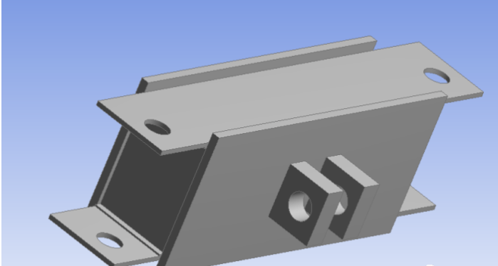
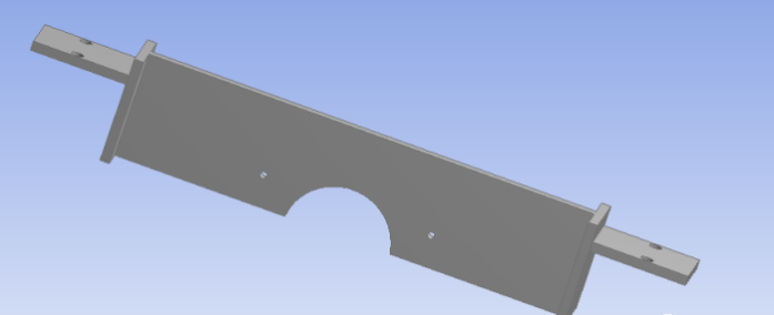
The cross beams on both sides of the frame body are channel steel butt welding. The top is covered with 20 mm thick steel plate, and the bottom is supported by I-beam. There are fixing seats at both ends of the cross beam to connect the two beams together. The right fixing seat provides support for the loading cylinder , In order to increase the versatility of the frame and adapt to different stroke cylinder tests, equidistant holes are opened on the beam of the frame to form a frame structure of different sizes. The fixed seat has a steel plate welded box-shaped structure. The middle part is connected with the rotary lug of the locking cylinder, and the two sides are connected with the frame. The fixed seat can slide back and forth along the beam and align the hole on the beam and insert the pin. Its structure as the picture shows. First, the collet is divided into upper and lower parts, and the contact surface with the cylinder is matted with felt, so as to ensure that the cylinder is not broken. The two ends of the plate are connected with the frame, and the cylinder is placed up and down. The specific structure of the collet as the picture shows.
There are two kinds of test head scheme designs. One is to use the lugs of the head of the locking hydraulic cylinder to connect with the head of the loading cylinder through a pin. The other is to design a pair of plugs so that the loading cylinder and the test cylinder are aligned through a plane. Flat structure. Through the connection of the lugs of the product, the loading section will rotate around the distal end during the loading process, and the phenomenon of upward warping will appear. Therefore, the plane contact topping test plan is selected, and the structure is shown in the figure.
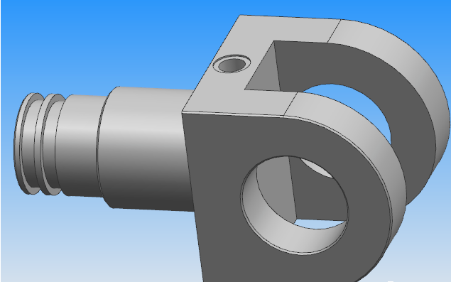
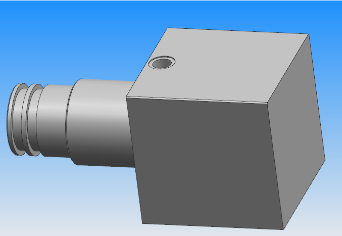
In order to verify the safety and reliability of the test device, a finite element model was established for the key components of the test device and finite element analysis was performed on it. The finite element results were analyzed based on the strength check theory. When the maximum stress of the key components of the test device was much lower than Under the premise that the allowable stress of the material fully meets the strength requirements, the thickness dimensions of related components should be appropriately reduced to save the production and manufacturing costs of the test device. Among them, the fixing seat and the collet are all directly stressed parts, so check their strength.
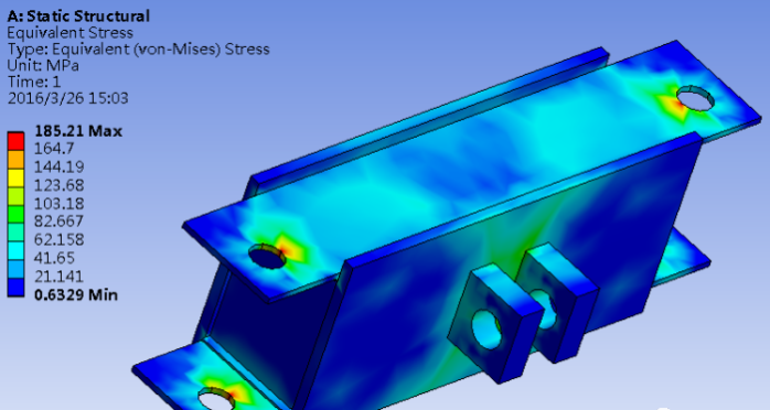
The loading force is 330 kN. Through finite element optimization, it is determined that the most reasonable steel plate thickness is welded to form the fixed seat. The fixed seat should be within the range of the force to withstand, and the thickness of the steel plate should be reduced as much as possible, thereby saving material costs. After optimizing the structure The results of the finite element analysis are shown in Figure 4. It can be seen that the maximum stress is 185 MPa, and the maximum stress is distributed at the round hole connecting the fixing seat and the frame. Q345A material is used. The yield limit of the material is 345 MPa, and the safety factor is 1.8, safe and reliable.
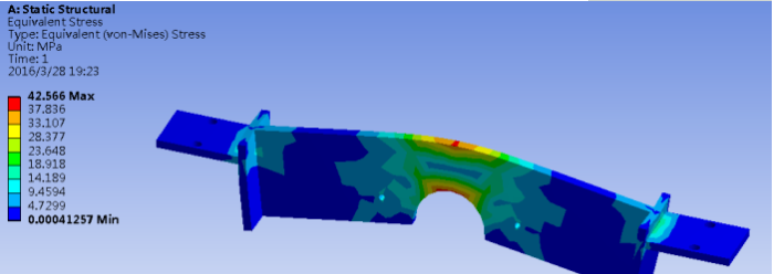
The collet stress is shown in the figure. The maximum stress is 42 pa, and the maximum stress is distributed at the contact part of the collet and the cylinder. It is welded with Q345A material. The yield limit of the material is 345 MPa, and the safety factor is 8.2, which is safe and reliable. The key performance items of the locking hydraulic cylinder are tested item by item, and the test results are listed in Table 3 to verify the key requirements of the vertical locking hydraulic cylinder to ensure that the product quality is foolproof.
Analyze and consult the erection hydraulic cylinder assembly drawings and test technical requirements, summarize the key performance requirements of erection hydraulic cylinder assembly, formulate process methods and test equipment guarantee measures, determine the application range of the device, formulate the design plan of the process device, and key components Design and verify 4 aspects to develop the vertical locking cylinder test device, and conduct tests on key test items to verify the test requirements and meet the product quality stability and reliability requirements.

