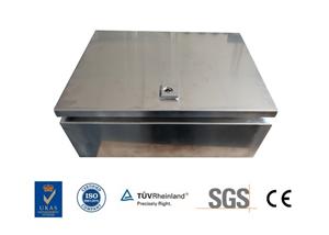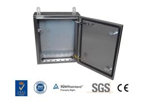
Build the bottom case of a control box with SolidWorks


This picture was modeled with SolidWorks2015 and rendered with KeyShot 8.
step
1. Draw a sketch on the front view.

2. Base flange, symmetrical on both sides: 150. Thickness: 1, radius: 0.25.

3. Edge flange, edit flange outline. Flange position: Bend out.

Modify sketch


4. Edge flange, edit flange outline. Flange position: Material is out.

Modify sketch


5. Edge flange, continue to edit the contour.


6. Miter flange, draw a sketch on the face pointed by the arrow.


7. Edge flange, edit contour.


8. Draw a circle on the left side. The diameter was later changed to 2.

9. Stretch cut and equal thickness.

10. Mirroring Features.

11. Sideline flange, given depth: 3.5.

12. Draw a straight notch and a center rectangle on the right side.

13. Stretch removal.

14. Still sketch on the side and draw straight notches.

10 arrays, spacing: 7, delete the middle ones

15. Stretch removal.

16. Draw a sketch on the left side of the cabinet.

17. Vent,
Boundary: the outermost circle;
Tendons: 4 straight lines;
Wing spar: two circles on the inside;

18. Draw another rectangle and stretch it out.

19. Expand.

20. Done.