Anti-deformation measures for large thin-walled parts
The main problem of processing thin-walled parts is the phenomenon of material deformation during processing. If plastic deformation occurs, the material cannot be further processed. The following will analyze the anti-deformation process of large thin-walled parts in detail and propose countermeasures.

Figure 1 Schematic of the processing of blanks and drilling positioning holes
Processing before improvement
A large-scale thin-walled part having an outer size of 2200 mm × 1650 mm × 70 mm and a wall thickness of 2-0.1 mm will be described as an example. The outline features are "open", the specific processing steps are shown in Figures 1 to 4.

Figure 2 Schematic diagram of the roughing inner cavity of the reverse side
Improved anti-deformation measures for tooling fixtures
Action one:
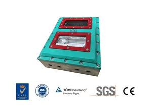
Design the vacuum fixture for the front and back machining. In order to make the front and back sides of the vacuum fixture match the plane dimensions of the cavities of the rough machining surface and to cooperate accurately, the three-dimensional digital model of the remaining wool parts after simulation is stored in the processing module of CATIA. Create a cgr format file, and then use the assembly module to import the tooling design module for analysis and comparison to check the fit of the vacuum fixtures and parts on both sides.

Figure 3 Schematic diagram of front part finishing

Fig. 4 Schematic diagram of reverse machining of parts
Measure two:
The three positioning hole bosses designed in the front finishing fixture, the positioning hole is φ12H7, one positioning hole is in the middle of the "open" shape, and the other two holes are located in the extension of the "open" shape. Side triangle, three-point positioning is stable.

Figure 5 Front and back perspective views of parts
Design three positioning holes in the vacuum fixture on the reverse side, φ20H7. The positioning coordinate systems on both the front and back sides are set at the position where the two holes are centered. The purpose is to make it easy to find the correct positioning during processing, and it is not easy to produce offset positioning differences. The parts are deformed. It is easy to adjust the positioning, and also adjust the parts. Minor deformation between φ12 and φ20 positioning holes.
Action three:
A groove with a depth of 10mm and a width of 30mm is designed at the contact part of the fixture and the part shape, so that when the shape of the part is processed with the pendulum, the tool can reach the bottom of the part to completely meet the processing requirements for cutting the surface size of the curved surface.

Figure 6 left side of the part
After testing, the standard flatness of the tooling must meet the accuracy requirement of 0.02mm. Due to the oversized parts, the vent holes need to be designed as φ14 holes. The sealing groove is designed as a semicircular groove with a depth of 5.5mm and a width of 6mm, and it must meet the sealing requirements.

Figure 7 Front and back processing effect
Cutting process:
HSK heat shrinkable tool holder is selected for high-speed cutting. After the tool holder is installed, a dynamic balance test is performed. When choosing coated carbide tools, in order to avoid overhang of the tool and vibration, select a tool with a short overhang as much as possible.
Anti-deformation processing process
The process arrangement can consider blanking, roughing, semi-finishing, and finishing as a whole, and design a reasonable anti-deformation processing process plan to optimize the overall process.

Figure 8 Schematic diagram of frontal finishing
The programming strategy uses rough machining and blanking together to consider removing a constant volume and cutting out the shape when machining on the reverse side. Semi-finish machining and finishing use constant milling to cut the thickness constantly, and then use the simulation processing software to perform theoretical programming detection and optimization, optimize the overhang length of the tool, optimize the cutting width and depth, the spindle speed and the actual processing parameters of the feed rate In order to improve the processing efficiency and avoid defect processing, the program can be more perfect and correct, and the processing process can be completely controlled to achieve the standards of safe, efficient and high-quality batch production.
The large-scale thin-walled parts anti-deformation processing technology mainly produces finished products from the overall material. There are reasonable anti-deformation fixture parameters, anti-deformation process arrangements and programming strategies. The purpose is to reduce the deformation of thin-walled structural parts and improve the processing quality.

Among them, two sets of anti-deformation fixtures and three-hole debugging methods. The method of finding the correct test to quickly determine the correct position of the part on the tooling and remove the amount of deformation generated by the part during processing. The simulation and optimization of the processing program have been verified by implementation. The anti-deformation technology is reasonable, the operation is simple, and it can meet the product quality requirements.