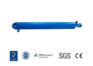
Leverless cylinder
Classification of rodless cylinders
1. Magnetic couple rodless cylinder
The piston drives the mobile body outside the cylinder to move synchronously by magnetic force.

Its working principle: Install a set of high-strength permanent magnetic ring on the piston. The magnetic field line acts through the thin-walled cylinder and another set of magnetic ring. Because the two sets of magnetic rings are magnetically opposite, they have a strong suction force. When the piston is pushed by the air pressure in the cylinder, under the action of magnetic force, the magnetic ring sleeve outside the cylinder is driven to move together. The thrust of the cylinder piston must match the suction of the magnetic ring

Buffer sealing ring 2. Magnetic ring 3. Buffer sleeve 4. Cylinder tube 5. Guide sleeve 6. Dust ring 7. Front end cover 8. Front air port 9. Magnetic switch 10. Piston rod 11. Wear ring 12. Piston Sealing ring 13. Rear end cover 14. Cushion adjustment bolt
SMC Magnetic Coupling Rodless Cylinder (CY Series) is a piston action in which a strong magnet is assembled in the cylinder barrel, and the magnetic force attracts the external slider action. The relationship between the magnetic force of the magnet slider inside and outside the cylinder, it is necessary to pay attention to the use pressure. Due to the magnetic coupling, there is no leakage. The use speed is from 50 to 70mm/s to medium speed.

2. Mechanical contact rodless cylinder
A groove is opened in the axial direction of the cylinder tube of the cylinder, and the piston and the slider move on the upper part of the groove. In order to prevent leakage and dust prevention, stainless steel sealing tape and dustproof stainless steel tape are used to fix the cylinder heads at both ends, and the piston frame passes through the groove to connect the piston and the slider. The piston is connected with the slider to drive the actuator fixed on the slider to realize reciprocating motion.

The SMC mechanically-joined rodless cylinder (MY series) is provided with a cutout in a part of the cylinder barrel, and the external slider and piston are engaged. A sealing tape is used to seal the cut part from the inside to form a cylinder container. The sealing tape of the slider part is bent inwards. Because it is easily affected by the surrounding environment, it is necessary to protect the sealing tape and the piston sealing ring. Therefore, a dust seal is installed. Due to the inability to completely seal the structure, there is usually a small amount of leakage. The use speed is from 80 to 100mm/s to high speed, and air cushion or hydraulic buffer can be used.

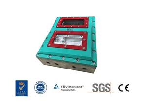
Clamping device of inclined wedge series force amplifying mechanism
It can be seen that a rectangular hole 1 is made in the middle of the rodless piston of the pneumatic cylinder, and the roller 1 connected to the lever is embedded in the rectangular radial hole 1 with an appropriate clearance. When the directional valve is in the left position as shown in the figure, compressed air enters the left cavity of the cylinder, the compressed air in the right cavity is released, the rodless piston moves to the right, and the roller 1 moves to the right, and at the same time, the roller 2 drives the double-sided inclined wedge Move to the right to push the right clamping wedge to clamp the right workpiece.
When the workpiece on the right is clamped, the compression wedge on the left is at the highest position under the action of the return spring, that is, the workpiece is released. Therefore, in the process of processing the right workpiece, the left workpiece can be loaded and unloaded. After the workpiece on the right is processed, the directional valve is switched to the right working state, the compressed air enters the right chamber of the cylinder, the roller 1 moves to the left, and the double-sided inclined wedge is driven to the left by the roller 2 to push the left pressure The inclined wedge clamps the workpiece on the left while releasing the workpiece on the right. That is, when the left workpiece is processed, the right workpiece can be loaded and unloaded.

Because the loading and unloading time coincides with the processing time, the production efficiency is significantly improved compared to the general fixture. If the machining process takes a long time, the wedge angle of the inclined wedge mechanism can be designed within the self-locking range. In this way, the compressed air supply to the cylinder can be stopped during the machining process, which is beneficial to extending the life of the cylinder and further saving energy.