General assembly process and requirements
一、Preparation before assembly
Working data: including general assembly drawings, component assembly drawings, part drawings, material BOM, etc., until the end of the project, the integrity of the drawings, neatness, and integrity of the process information records must be guaranteed.
2. Work site: Parts placement and component assembly must be carried out within the specified work site. The site for the placement and assembly of the whole machine must be clearly planned until the end of the entire project. All work sites must be neat, standardized and orderly.
3. Assembly materials: Before the operation, the assembly materials in accordance with the assembly process must be in place on time. If some of the non-deterministic materials are not in place, you can change the order of operations and then fill in the material reminder form to the purchasing department.
4. Before assembling, you should understand the structure, assembly technology and process requirements of the equipment.
二、Basic Specifications
Mechanical assembly should be carried out in strict accordance with the assembly drawings and process requirements provided by the design department. It is strictly forbidden to modify the contents of the operation or modify the parts in an abnormal way.
2. The assembled parts must be qualified parts accepted by the quality inspection department. If unqualified parts are found missing during the assembly process, they should be reported in time.
3. The assembly environment requires clean, no dust or other pollution, and parts should be stored in a dry, dust-free place with protective pads.
4. During the assembly process, the parts shall not bump, cut, or damage the surface of the parts, or cause the parts to bend, twist, or deform obviously, and the mating surfaces of the parts shall not be damaged.
5. For parts with relative movement, lubricating oil (grease) should be added between the contact surfaces during assembly.
6. Matching dimensions of matching parts must be accurate
7. When assembling, parts and tools should have special placement facilities. In principle, parts and tools are not allowed to be placed on the machine or directly on the ground. If necessary, protective pads or carpets should be placed on the place.
8. In principle, it is not allowed to step on the machine during assembly. If you need to step on the machine, you must lay protective pads or carpets on the machine. It is strictly forbidden to step on important parts and non-metallic low strength parts.
三、Connection method
1.Bolt connection
(1) When tightening bolts, an adjustable wrench is not allowed, and no more than one same washer should be used under each nut. After the countersunk head screws are tightened, the nail heads should be buried in the machine parts and should not be exposed.
(2) Under normal circumstances, the threaded connection should have anti-loosening spring washers, the method of tightening symmetrical multiple bolts should be gradually tightened in a symmetrical order, and the bar-shaped connectors should be gradually tightened symmetrically in both directions from the middle.
(3) After the bolt and nut are tightened, the bolt should expose 1 to 2 pitches of the nut; when the screw does not need to be disassembled when fastening the motion device or maintenance, the screw should be coated with thread glue before assembly.
(4) Fasteners with specified tightening torque requirements should be tightened with torque wrenches according to the specified tightening torques.
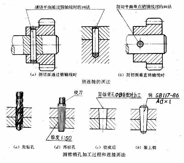
2. Pin connection
(1) The end face of the positioning pin should be slightly higher than the surface of the part. After the cone pin with screw tail is installed into the relevant part, the large end should be sunk into the hole.
(2) After the cotter pin is inserted into the relevant parts, its tail should be separated by 60 ° ~ 90 °
3. Bonding
(1) The two sides of the keyway of the flat key and the fixed key should be evenly contacted, and there should be no gap between their mating surfaces.
(2) After the clearance-fitted key (or spline) is assembled, there should be no uneven tension when the relatively moving parts move along the axial direction.
(3) After the hook key and the wedge key are assembled, the contact area should not be less than 70% of the working area, and the non-contact part should not be concentrated in one place; the length of the exposed part should be 10% to 15% of the length of the slope.
4. Riveting
(1) The materials and specifications of the riveting must meet the design requirements, and the processing of the rivet holes should comply with the relevant standards.
(2) During riveting, the surface of the riveted parts must not be damaged or deformed.
(3) Unless there are special requirements, there should be no looseness after riveting. The head of the rivet must be in close contact with the part to be riveted and should be smooth and round.
5. Expansion sleeve connection
Expansion sleeve matching: apply grease to the expansion sleeve, put the expansion sleeve into the hub hole of the assembly, adjust the assembly position after fitting the installation shaft, and then tighten the bolts. The tightening order is bounded by the slit, and the left and right cross symmetry is tightened in order to ensure that the rated torque value is reached.
6. Tighten the connection
The tapered end of the set screw and the hole should be 90 °, and the set screw should be tightened to the hole.
四、Assembly of rolling bearings
1. Before the bearing is assembled, there must be no dirt on the bearing.
2. When assembling the bearing, apply a layer of lubricating oil to the surface of the mating parts. The non-model end of the bearing should face inward, that is, in the direction of the shaft shoulder.
3. Use special pressing tools when assembling the bearings. It is strictly forbidden to assemble by direct hitting. The size, direction and position of the forcing force when setting the bearings should be appropriate. The protection frame or rolling elements should not be stressed and should be evenly and symmetrically. To ensure that the end face is perpendicular to the axis.
4. The end surface of the inner ring of the bearing should generally be close to the shaft shoulder (shaft clamp). After the outer ring of the bearing is assembled, the contact between the bearing cover at the positioning end and the washer or outer ring should be uniform.
5. After the rolling bearing is installed, the rotation of the relative moving parts should be flexible and light. If there is a stuck phenomenon, the cause of the problem should be checked and analyzed and dealt with accordingly.
6. In the process of bearing assembly, if the hole or shaft fit is found to be too loose, the tolerance should be checked; when it is too tight, brutal assembly should not be forced, and the cause of the problem should be analyzed and dealt with accordingly.
7. The axial clearance of single-row tapered roller bearings, thrust angular contact bearings and bidirectional thrust ball bearings meets the drawings and process requirements during assembly
8. For bearings and surfaces matched with grease, appropriate grease should be injected after assembly. For bearings with operating temperature not exceeding 65 ℃, ZG-5 grease can be used according to GB491-65 "Calcium-based Grease"; for bearings with operating temperature higher than 65 ℃, it can be used according to GB492-77 "Calcium-based grease" ZN-2ZN-3 grease.
9. The temperature rise of ordinary bearings should not exceed 35 ° C during normal operation, and the maximum temperature during operation should not exceed 70 ° C.
五、 Assembly of linear bearings
1. Before assembling, grease should be applied to the inside of the bearing.
2. When the bearing is pressed into the support base, a special installation tool should be used to press against the end face of the outer ring, and it is not allowed to knock the bearing directly to avoid deformation.
3. The cooperation between the bearing and the support must meet the tolerance requirements. Too tight will make the guideway shaft and the bearing interference fit, which will damage the bearing; too loose will prevent the bearing from being fixed in the support.
4. When inserting the guide shaft into the bearing, gently insert it into the center. If it is inserted at an angle, the balls will fall off and the cage will deform.
5. When the bearing is installed in the support base, it is not allowed to rotate. Forcing the rotation will damage the bearing.
6. It is not allowed to directly tighten the set screw on the outer ring of the bearing, otherwise it will deform.
六、 Assembly of linear guides
The mounting part of the guide rail must not be dirty, and the flatness of the mounting surface must meet the requirements.
2. When there is a reference edge on the side of the guide rail, it should be installed close to the reference edge. When there is no reference edge, the sliding direction of the guide rail should be consistent with the design requirements. After the fixing screws of the guide rail are tightened, the slide direction of the slider should be checked for deviation, otherwise Must be adjusted.
3. If the slider is driven by a transmission belt, after the transmission belt and the slider are fixed and tensioned, the transmission belt must not be inclined, otherwise the pulley must be adjusted so that the driving direction of the transmission belt is parallel to the guide rail.