Factors to consider in thread processing
Thread as one of the main connection and transmission applications in machinery, its role can not be ignored. In different applications, the appropriate thread form and processing method should be selected.
The main function of the thread
-Achieve mechanical coupling
-Pass motion by converting rotary / linear motion into linear / rotary motion
-Achieve mechanical benefits; use less force to generate greater force.
Thread profile
The thread profile defines the geometry of the thread, including part diameters (large, medium, and small), thread profile angle, pitch, radius, and helix rise angle.
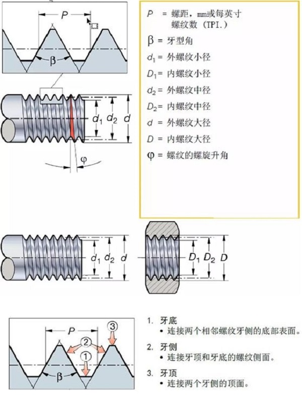
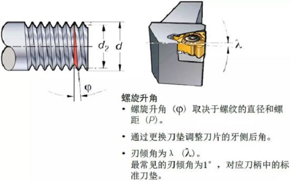
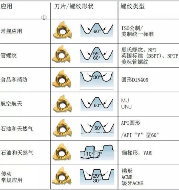
The most common thread profile:
Thread processing method
There are various thread processing methods and tools suitable for different parts, thread profiles and pitches. Each threading method and tool has its own advantages in specific situations. Before you start, you need to integrate the initial considerations for threading.
Thread:
Consider the following dimensions and quality requirements for the thread to be machined:
• Male or female?
• Thread profile (e.g. metric, UN)
• Pitch right or left?
• Number of threads
• Tolerance (tooth shape, position)
Components:
After considering the features, observe the part:
• Can the workpiece be clamped safely?
• Is chip removal or chip control a key issue?
• Does the material have good chip breaking characteristics?
• Part production batch.
• Single or multiple thread
machine tool:
Machine tool considerations include:
• Stability, power and torque, especially for larger diameters
• Cutting fluid and coolant supply
• Do you need high-pressure coolant to break long chips?
• Number of available tool positions suitable for the selected threading method
• Speed limit, especially for bar feeders and small diameters
• Clamping possibilities, is there a counter-spindle or tailstock?
• Is there a threading cycle?
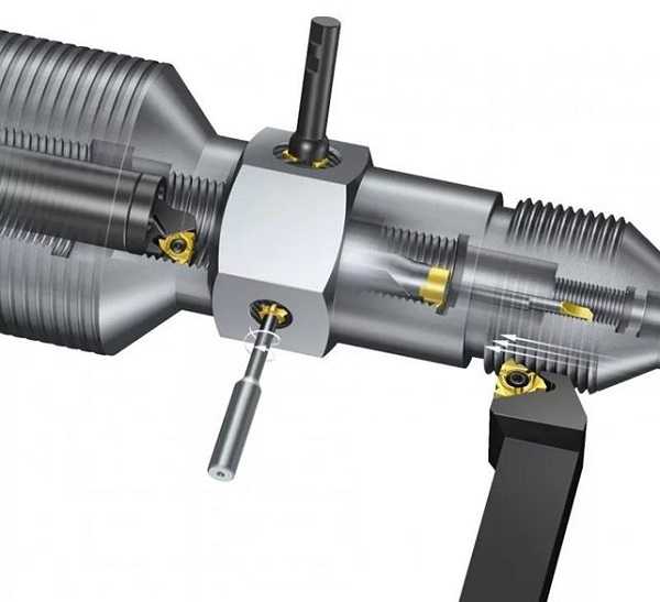
Thread processing method
Each threading method has its own advantages in specific situations.
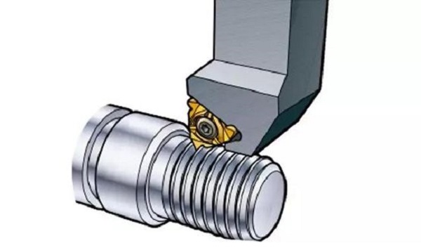
Thread turning
• High productivity thread processing method
• Machining threads on parts that rotate around the center of rotation
• Covers the largest number of thread profiles
• Provides good surface quality and thread quality
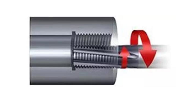
2.Thread milling
• Machining threads for non-rotating parts, machining threads outside the center of rotation of rotating parts
• Interrupted cutting ensures good chip breaking performance when processing all materials
• Low cutting forces make it possible to machine threads in long overhangs and thin-walled parts
• Ability to machine threads near the shoulder or bottom without using undercuts
• Can process large workpieces that are not easy to install on a lathe
• Capable of processing large diameter threads with low power and torque requirements
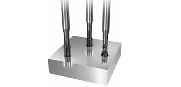
3. Tapping
• High productivity and economical thread processing method, especially suitable for processing smaller threads
• Covers the most commonly used thread profiles
• Suitable for a variety of machine tools, capable of processing both rotating and non-rotating parts
• A wide range of material-specific products ensures good chip control
• Easy to perform deep hole thread processing
• can be formed thread processing
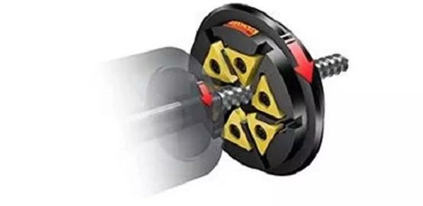
4.Thread cyclone milling
• Suitable for slender parts such as screws
• Ability to process high-quality threads without bending
• Only a single pass can remove all the surplus, thereby shortening the production cycle
• Machining precise threads by tilting the cyclone cutter head to the helical rising angle
• Good chip control enables more continuous high-productivity machining
• Requires a machine with thread cyclone milling capabilities
During the machining process, we also have to continuously check and correct, and perform accurate calculations. Finally, there are some comprehensive knowledge points of the post-thread processing process:
Some key factors to consider in thread turning:
• Check whether the workpiece diameter has the correct machining allowance before thread turning, and add 0.14mm as the crown allowance.
• Position the tool precisely in the machine.
• Check the setting of the cutting edge relative to the middle diameter.
• Make sure you use the correct blade geometry (A, F, or C).
• Ensure that there is sufficient and even clearance (blade-to-shim inclination angle) by choosing the right shim to obtain the correct flank clearance.
• If the thread fails, check the entire clamping including the machine.
• Check the CNC programs available for thread turning.
• Optimize feed method, number of passes and size.
• Ensure correct cutting speed to meet application requirements.
• If the pitch of the workpiece thread is incorrect, check that the machine pitch is correct.
• It is recommended that the tool be started with a minimum pitch of 3 times the pitch before plunging into the workpiece.
• High-precision coolant extends tool life and improves chip control.
• Quick-change system ensures easy and quick clamping.
• For optimal productivity and tool life, multi-tooth inserts are preferred, full-tooth single-edged inserts are the second choice, and V-tooth inserts are the third choice.
Tapping hole size and tolerance:
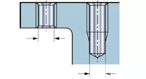
Basic calculation of cutting tap hole size:
D = TD-TP
D = aperture
TD = nominal thread diameter
TP = pitch
Example: The hole size of M10 x 1.5 cutting tap is 10-1.5 = 8.5mm
Basic calculation of the size of the bottom hole of the extrusion tap:
D = TD-(TP / 2)
D = aperture
TD = nominal thread diameter
TP = pitch
Example: The drill size of M10 x 1.5 extrusion tap is 10- (1.5 / 2) = 9.3mm

