Dimensioning rules for mechanical drawings
basic rules
1. The actual size of the machine should be based on the size value noted on the drawing, and has nothing to do with the size of the graphic and the accuracy of the drawing.
2. For the dimensions in the drawings (including technical requirements and other instructions), when the unit of mm is used, the code or name of the measurement unit need not be marked. If other units are used, the code or name of the corresponding measurement unit must be indicated.
3. The dimensions marked in the drawing are the last completed dimensions of the parts shown in the drawing, otherwise it should be explained separately.
4. Each dimension of the machine is generally marked only once, and it should be marked on the graph that reflects the clearest structure.
Size composition
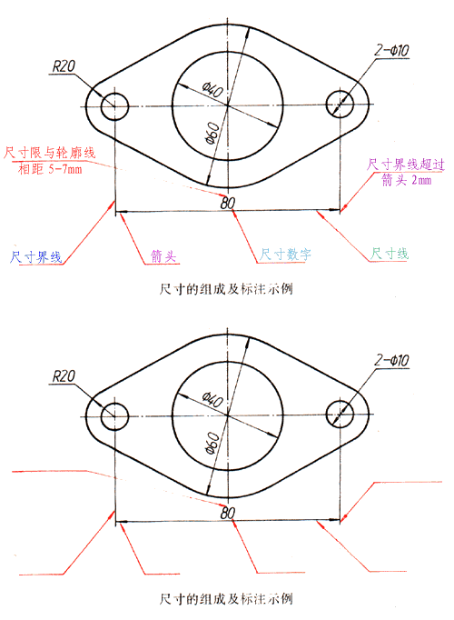
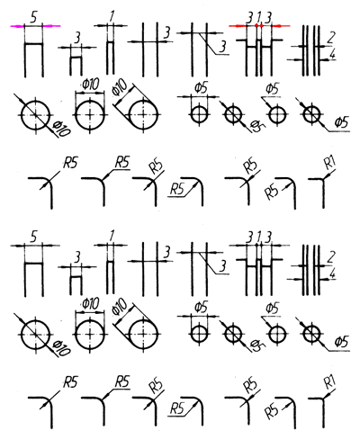
As shown in the figure below, a complete dimension should generally include dimension numbers, dimension lines, extension lines, and arrows or diagonal lines that indicate the end of the dimension line.
1.Size numbers
Linear dimension numbers should generally be written above the dimension line, but also allowed at the break of the dimension line.
2. Dimension line
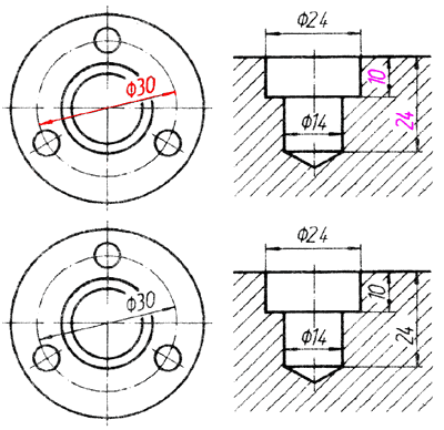
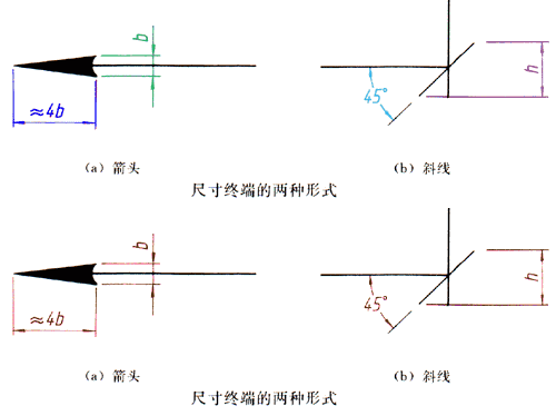
Dimension lines are drawn with thin solid lines and cannot be replaced by other graph lines. Generally, they should not overlap with other graph lines or be drawn on their extension lines. When dimensioning linear dimensions, the dimension line must be parallel to the marked line segment; when there are several dimension lines parallel to each other, the large dimension should be noted outside the small dimension to prevent the dimension line from intersecting with the extension line. When dimensioning the diameter or radius on a circle or arc, the dimension line should generally pass through the center of the circle or the extension line. There are two forms of the end of the dimension line, as shown in the figure: the arrow is suitable for various types of patterns, b in the figure is the width of the thick solid line; the diagonal line is drawn with a thin solid line, and h in the figure is the font height. The end of the dimension line of the circle diameter, arc radius and angle shall be drawn as an arrow. When using oblique lines, the dimension lines and extension lines must be perpendicular to each other.
3. Extension line
The extension lines are drawn with thin solid lines and should be drawn from the contour line, axis or symmetrical centerline of the figure. You can also use contour lines, axes, or symmetrical centerlines as extension lines. The dimension extension line should generally be perpendicular to the dimension line and extend about 2 mm beyond the end of the dimension line.
Example of dimensioning
The following are some of the dimensional annotations required by the national standard:
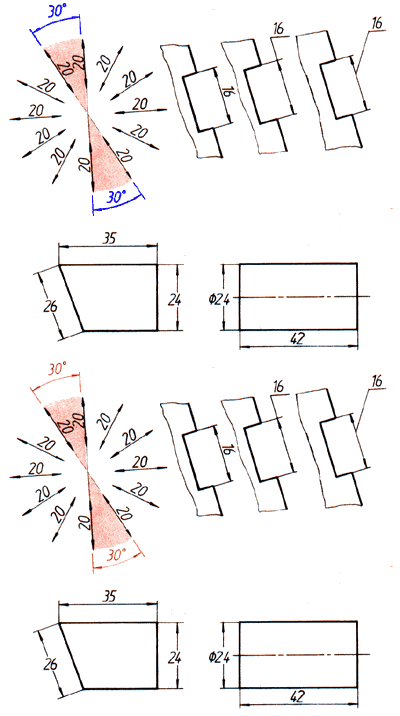
Number direction for linear dimensions
The first method: the dimension numbers should be written in the direction shown in the upper left figure, and as far as possible, avoid dimensioning in the range shown in the figure 30. When it is unavoidable, it can be marked in the form of the upper right figure.
The second method: when there is no misunderstanding, for non-horizontal dimensions, the numbers can be written horizontally at the break of the dimension line, as shown in the two figures below. In a drawing, the same method should be used as much as possible, and the first method should be used for annotation.
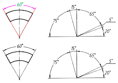
angle
The extension line should be drawn in the radial direction. The extension line is drawn as an arc, and the center of the circle is the vertex of the angle. Dimension numbers should be written horizontally, generally noted at the break of the dimension line, if necessary, it can also be marked in the form on the right.
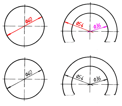
circle
The diameter of a circle should generally be noted according to these two examples.
Arc
The radius of the arc should generally be noted according to these two examples.
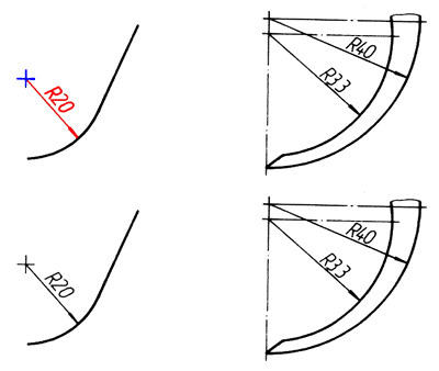
Great arc
When the center of the circle cannot be marked within the scope of the drawing, the left icon can be used for annotation; when the center of the circle is not required to be marked, the right icon can be used for annotation.
Small size
As shown in the legend above, when there is not enough space, the arrows can be drawn outside, or two arrows can be replaced with small dots; the size numbers can also be written outside or drawn out. For small sizes of circles and arcs, you can press the two icon icons to note.
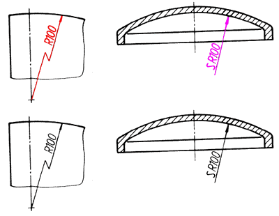
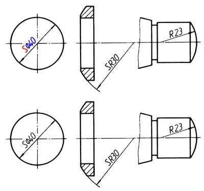
Spherical
Mark the size of the spherical surface, as shown in the two figures on the left, and add "S" before ø or R. If it does not cause misunderstanding, it can be omitted, such as the right end spherical surface in the right figure.
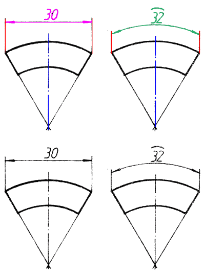
Chord and arc length
When labeling the chord length and arc length, as shown in these two examples, the bounded line should be parallel to the vertical bisector of the chord. When marking the length of an arc, use a circular arc for the dimension line, and the symbol "^" should be added above the dimension number.
Draw only symmetrical parts at half or more
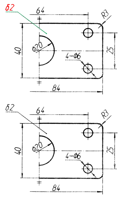
Dimensions 84 and 64 on the drawing. Their dimension lines should slightly exceed the symmetrical centerline or the boundary line of the break. Thin solid line (symmetric symbol).
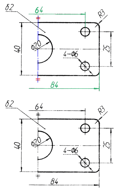
Plate parts
When dimensioning a plate-shaped part, the symbol "8" can be added to the thickness dimension number as shown in the example figure.
Dimensions at smooth transitions
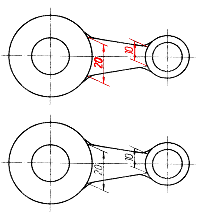
As shown in the example, at the smooth transition, the contour lines must be extended with thin solid lines, and the extension lines are drawn from their intersections.
Allow ruler line to tilt
The extension line should generally be perpendicular to the extension line, and it can be tilted if necessary. Still as shown in the example above, if the extension line here is perpendicular to the dimension line, the figure line is very unclear, so tilting is allowed.
Square structure
As shown in the example figure, when marking the cross section of the machine as the size of the square structure, the symbol “□” can be added before the number of the side length dimension, or “□ 14” can be replaced by 14 × 14. The two thin solid lines that intersect in the figure are plane symbols (when a graphic cannot fully express a plane, this symbol can be used to represent a plane).

Slope and taper
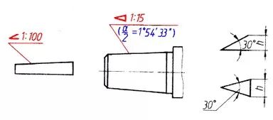
The slope and taper can be marked with the method shown in the two examples below. The direction of the symbol should be the same as the direction of the slope and taper. Taper can also be injected on the axis. Generally, it is not necessary to note the angle value (a is the cone angle) while marking the taper; if necessary, you can note the angle value in parentheses as shown in the illustration.
The drawing of the slope and taper symbols is shown in the two figures on the right. The line width of the symbol is h / 10, and h is the word height.
What to do when the figure passes the size number
Dimension numbers cannot be passed by any drawing lines. When dimensional numbers cannot be passed by the drawing lines, the drawing lines must be broken, as shown in the illustration.
